
If you’re managing a network and struggling with limited connectivity options from your ISP, like a single fiber uplink, an ISP router that lacks robust features or only one port with the required bandwidt, this discussion is for you. We’re going to explore how Cisco Meraki switches and firewalls can help overcome these challenges. Our focus will be on enhancing network resilience and efficiency, ensuring your setup can handle whatever your ISP throws your way. These constraints can lead to several issues:
- Lack of Redundancy: Without multiple uplinks, it’s difficult to ensure network reliability and continuous service.
- High-Availability Requirements: For a high-availability setup to function properly with one or more ISP uplinks, it’s essential that each firewall in the pair is connected to an uplink. This ensures that the system can maintain continuous operation, even if one firewall fails.
- Throttled Bandwidth: If the ISP router has only one port with >=10GbE and it is connected to the primary firewall, the secondary firewall may only be able to connect via a 1GbE port.
Cisco Meraki Solutions Overview
When integrating Cisco Meraki technology into your network, the approach can vary based on the type of equipment and connectivity your ISP provides. Here are two common scenarios you might encounter, each requiring a different strategy:
- ISP Provides a Router with Multiple Ports: In this scenario, your ISP supplies a router equipped with several ports, offering multiple points for network connections. This setup allows creating a redundant network path to each firewall in the pair.
- ISP Provides a Router with a Single Port: Here, the ISP’s router offers only one port or just one of the ports comes with 10GbE. To configure high availability (HA) with two Meraki firewalls, a WAN switch will be necessary to split the single ISP connection between the two firewalls, ensuring both can maintain an active link for redundancy.
In the following sections, we will dive deeper into the specific configurations and necessary equipment adjustments to accommodate each of these ISP scenarios, focusing on maintaining high availability and optimizing network performance.
Minimum IP Address Allocation
For the HA setups discussed, you will need at least four public WAN IP addresses from your ISP:
- One IP for the ISP Router: Assigned to the WAN interface of the ISP’s router connecting to your network. This IP serves as the gateway for your network traffic to the internet.
- One Virtual IP (vIP): Used as a shared IP address between the two Meraki firewalls in your HA pair. The vIP handles both inbound and outbound communication, ensuring external devices always interact with a single IP address, even during a firewall failover.
- One IP for Firewall 1: Assigned to the WAN interface of the primary Meraki firewall. This IP is used for management purposes, including communication with the Meraki dashboard.
- One IP for Firewall 2: Assigned to the WAN interface of the secondary Meraki firewall. Similar to Firewall 1, this IP facilitates management tasks and dashboard communication when this firewall is active.
Detailed Solution Walkthrough
To effectively implement Cisco Meraki solutions across different ISP scenarios, it’s crucial to visualize how each setup connects and operates within the network. We’ll use a single comprehensive network topology drawing that illustrates all ISP scenarios, clearly distinguishing the configurations necessary for each. This visual guide will help you navigate the specifics of setting up your network for high availability using Cisco Meraki equipment, regardless of the ISP setup.
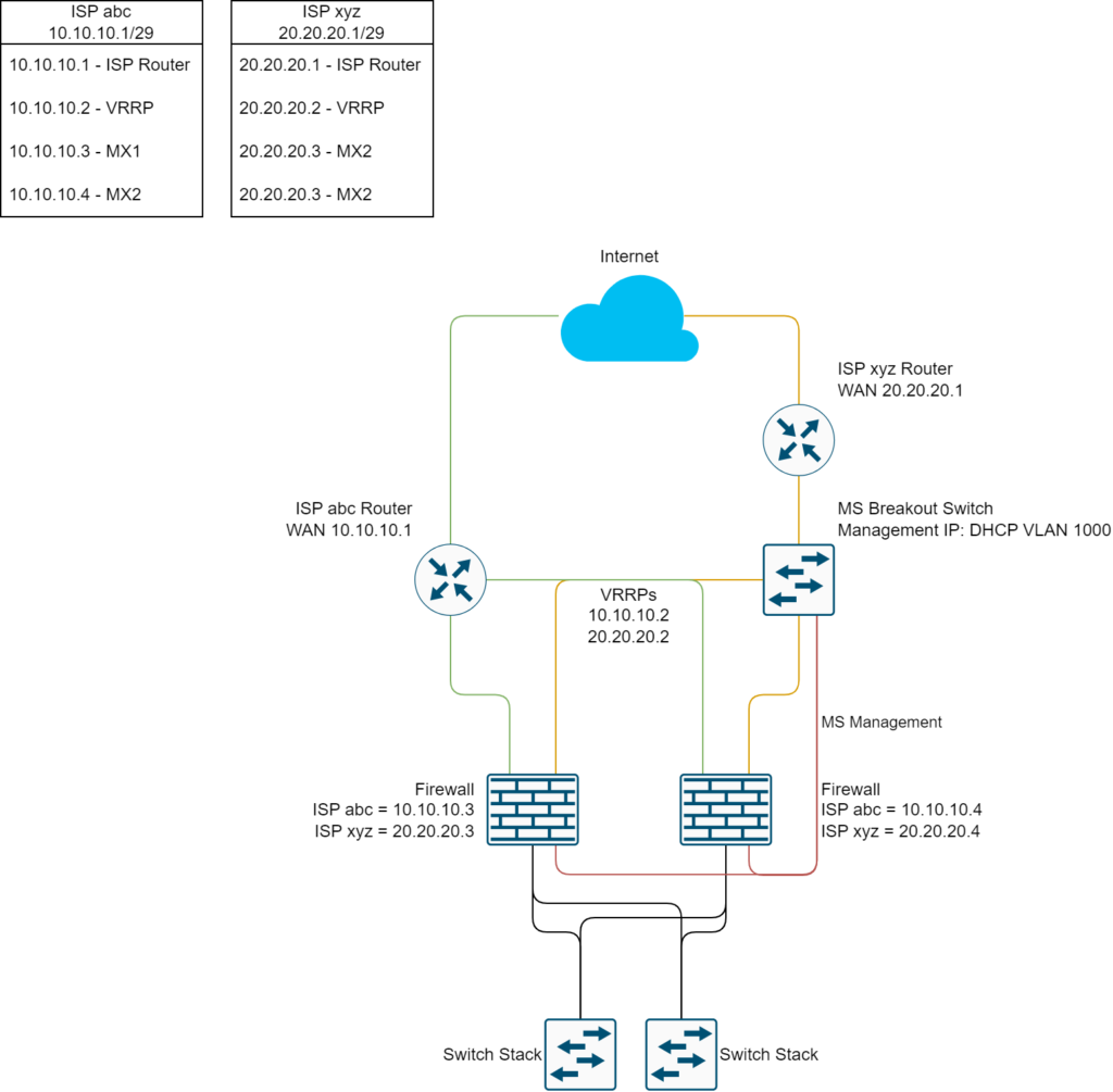
Network Topology Drawing Overview
- Visual Elements: The drawing will show two distinct areas, each representing one of the ISP scenarios: a router with multiple ports, a router with a single port. Each section will depict the connections to a WAN switch and the subsequent link to two Meraki firewalls in an HA setup.
Scenario Descriptions
- ISP-Provided Router with Multiple Ports
- Connectivity: The ISP router’s multiple ports connect to both firewalls directly.
- Configuration Goals: Focus on how to leverage multiple ports for effective load balancing and failover capabilities.
- ISP-Provided Router with a Single Port
- Connectivity: The single port from the ISP router connects to a WAN switch, which splits the connection to both Meraki firewalls.
- Configuration Goals: Details on configuring the WAN switch to handle the single ISP link effectively and setting up the Meraki firewalls for seamless redundancy.
Step-by-Step Configuration for Each Scenario
- Detailed Instructions: For each area in the topology drawing, we will provide specific setup steps, highlighting the unique requirements and adjustments needed to optimize each configuration.
- Key Considerations: Special attention will be given to ensuring network resilience, scalability, and managing potential points of failure in each scenario.
This unified approach not only simplifies the understanding of different setups but also ensures that you have a clear path to implementing a robust network with high availability, tailored to your specific ISP conditions.
ISP-Provided Router with Multiple Ports
In this scenario, your ISP supplies a router equipped with multiple ports, allowing direct connections to each of your Meraki firewalls in a high-availability (HA) pair. This setup simplifies redundancy and enhances network reliability since each firewall can independently connect to the ISP’s network.
Connectivity Setup overview
- Direct Connections: Connect each Meraki firewall’s WAN interface directly to a separate port on the ISP’s router.
- IP Address Allocation: Obtain multiple public IP addresses from your ISP—one for each firewall’s WAN interface. This ensures both firewalls can operate simultaneously and take over if the other fails.
- Load Balancing and Failover: Configure the Meraki firewalls to manage traffic efficiently, utilizing both connections for load balancing and ensuring seamless failover.
Configuration Steps
- Physical Connections:
Check your ISP router settings if all ports are configured for public IP address distribution, if necessary change the configuration.- Firewall 1: Connect its WAN port to Port 1 on the ISP router.
- Firewall 2: Connect its WAN port to Port 2 on the ISP router.
- Firewall Settings:
- WAN Interfaces: Assign unique public IP addresses to each firewall’s WAN interface, as provided by the ISP.
- Go to Security & SD-WAN > Monitor > Appliance Status > Uplink
- Configure each WAN uplink and set a static public IP from your address block. Repeat these steps for the spare firewall.

- High Availability (HA) Setup:
- Navigate to the Meraki dashboard.
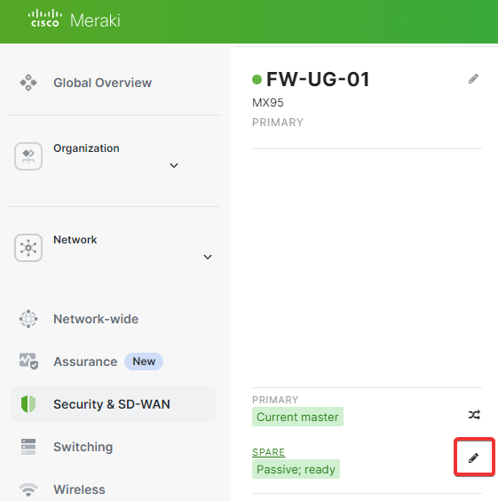
- Go to Security & SD-WAN > Monitor > Appliance Status.
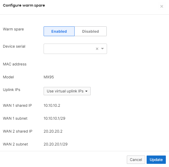
- Click on the Edit symbol and Enable Warm Spare (using VRRP).
- Ensure both firewalls have the virtual uplink IP (shared IP) configured for seamless failover. This configuration might take a few minutes to apply.
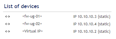
- Afterwards, the device table on your ISP router should look like this:
- Load Balancing (Optional):
- Configure load balancing if your ISP supports it, distributing outbound traffic between both firewalls. If needed, go to Security & SD-WAN > SD-WAN & traffic shaping > Uplink selection.
- WAN Interfaces: Assign unique public IP addresses to each firewall’s WAN interface, as provided by the ISP.
- Testing the Setup:
- Failover Test: Disconnect Firewall 1 to ensure Firewall 2 takes over without service interruption.
- Load Balancing Verification: Monitor traffic to confirm it’s appropriately balanced across both connections.
Benefits of This Setup
- Enhanced Redundancy: Direct connections reduce dependency on additional hardware, minimizing potential points of failure.
- Simplified Configuration: Fewer devices mean a more straightforward setup and maintenance process.
- Optimized Performance: Direct ISP connections can offer better bandwidth utilization and lower latency.
ISP-Provided Router with a Single Port
When the ISP provides a router with only a single port—or only one port with the required bandwidth—you’ll need to introduce a WAN switch to distribute the connection to both Meraki firewalls. This setup ensures both firewalls have access to the WAN link, maintaining high availability despite the ISP’s hardware limitations.
Connectivity Setup overview
- Implementing a Meraki WAN Switch: Place a managed switch between the ISP router and your Meraki firewalls. To avoid loops, complete the configuration before connecting every port.
- Management VLAN (VLAN1000):
- Configure VLAN1000 as the dedicated management VLAN on the switch.
- Connect both firewalls (LAN) to this VLAN for centralized management and monitoring.
- Physical Connections:
- ISP Connection: Connect the ISP router’s single port to the appropriate port (e.g. 10G org mGig Port) on the Meraki WAN switch. We’ll use VLAN1 for the WAN segment.
- Firewall Connections:
- Connect Firewall 1’s WAN port to the Meraki WAN switch.
- Connect Firewall 2’s WAN port to the Meraki WAN switch.
Visualization
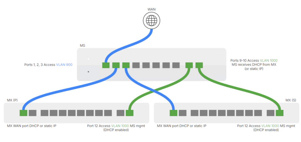
ref: MX, MS – WAN Breakout Switch – Google Präsentationen
Configuration Steps
- Meraki WAN Switch Setup:
- Add the Switch to a new Network:
- Create a new Meraki Network to avoid topology issues.
- Claim the Meraki switch in your Meraki dashboard under Organization > Inventory.
- Add the switch to your network under Network-wide > Add devices.
- VLANs and Ports
- Ensure to set every port as access and both management uplink ports have STP loop guard enabled and UDLD set to enforce.
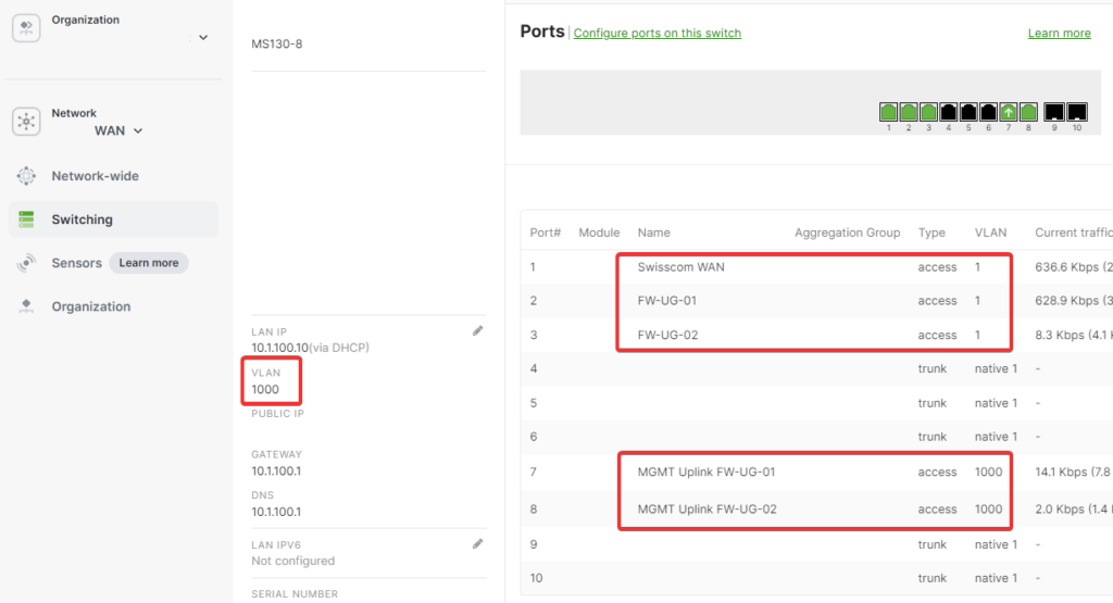
- Ensure to set every port as access and both management uplink ports have STP loop guard enabled and UDLD set to enforce.
- Power Redundancy (Optional):
- Select a switch with dual power supplies or connect it to a UPS for increased reliability.
- Add the Switch to a new Network:
- Firewall Settings:
- WAN Interfaces: Assign unique public IP addresses to each firewall’s WAN interface, as provided by the ISP.
- Go to Security & SD-WAN > Monitor > Appliance Status > Uplink
- Configure each WAN uplink and set a static public IP from your address block. Repeat these steps for the spare firewall.
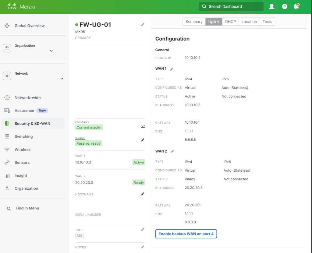
- High Availability (HA) Setup:
- Navigate to the Meraki dashboard.
- Go to Security & SD-WAN > Monitor > Appliance Status.
- Click on the Edit symbol and Enable Warm Spare (using VRRP)
- Ensure both firewalls have the virtual uplink IP (shared IP) configured for seamless failover. This configuration might take a few minutes to apply.
- WAN Interfaces: Assign unique public IP addresses to each firewall’s WAN interface, as provided by the ISP.
- Testing the Setup:
- Failover Test:
- Simulate a failure on Firewall 1 by disconnecting it.
- Verify that Firewall 2 assumes the active role without disrupting network services.
- Connectivity Check:
- Ensure both firewalls can reach the internet through the WAN switch when active.
- Ensure both firewalls can reach the internet through the WAN switch when active.
- Failover Test:
Benefits of This Setup
- High Availability Maintained: Overcomes the ISP’s hardware limitations to provide a resilient network.
- Cost-Effective Solution: Avoids the need for expensive ISP hardware upgrades by using an affordable switch.
Considerations
- Single Point of Failure: The WAN switch becomes critical. Mitigate risks by:
- Using High-Quality Hardware: Invest in a reliable switch from a reputable manufacturer.
- Redundancy: Consider stacking two switches for redundancy if supported.
Conclusion
Navigating the complexities of network configurations, especially when faced with ISP-imposed limitations, can be challenging. However, as we’ve explored, Cisco Meraki switches and firewalls provide flexible solutions to enhance your network’s resilience and efficiency. By tailoring your setup to your specific ISP scenario, whether they provide a router with multiple ports or a single port, you can establish a robust high-availability infrastructure.
Tested Swiss ISP
The configurations and solutions outlined in this discussion have been tested and validated with several leading Swiss Internet Service Providers (ISPs). This ensures that the high-availability setups using Cisco Meraki switches and firewalls are compatible and effective within the Swiss networking environment. The following ISPs have been confirmed to support the configurations described:
- Swisscom (Centro Business 2.0 and 3.0 Router)
- iWay (Mikrotik RB3011UiAS-RM)
- SASAG (Cisco ISR 1100)
- Init7 (MikroTik CRS310)
By collaborating with these ISPs, we’ve verified that they accommodate the necessary technical requirements, such as supporting virtual MAC addresses and allowing for HA configurations without restrictive policies. This compatibility ensures that you can confidently implement the solutions discussed, knowing they have been proven to work effectively with these providers.
Resources and Further Reading
- Visualizations of WAN Switch topologies: MX, MS – WAN Breakout Switch – Google Präsentationen
- Meraki Documentation: MX Warm Spare – High-Availability Pair – Cisco Meraki Documentation
Schreiben Sie einen Kommentar